Modern applications rely on structured storage systems that can scale, stay reliable, and keep data consistent. At the heart of all of it sits the data model. It defines how information is organized, stored, and retrieved. Get the model wrong and performance suffers, integrity breaks down, and future changes become painful. Get it right and everything else becomes easier to manage.
Here, we’ll take a practical look at database data models, from types and abstraction levels to normalization and design. We’ll walk through how an ER diagram turns into real tables, using SQL and real scenarios to ground the theory. In this article, we’ll bridge DBMS concepts with hands-on database design.
Table of contents
- What Is a Data Model in DBMS?
- Types of Data Models in DBMS
- Data Modeling Abstraction Levels
- Key Components of a DBMS Data Model
- The Entity-Relationship (ER) Model
- Key Components (Primary/Foreign Keys, Constraints)
- Sample Student Management Database (MySQL Example)
- Inserting Sample Data
- Normalization in DBMS
- Advantages and Disadvantages of Data Models
- Conclusion
- Frequently Asked Questions
What Is a Data Model in DBMS?
A data model defines the logical structure of a database. The system defines how data elements within the database system will connect with each other while maintaining specific constraints. For example, a data model demonstrates that a student entity contains attributes such as StudentID and Name while showing that a Course entity connects to Student through an enrollment relationship. The model defines which data we keep and the rules that regulate its management.
Data models enable teams to create data representation plans through logical design instead of starting with SQL tables. The method decreases mistakes while enhancing communication and making subsequent modifications easier.
Key roles of a data model include:
- Structure: The system needs to arrange data into entities and fields which represent tables and columns in a coherent structure.
- Relationships: The system shows how data elements connect with each other through its ability to express that students can enroll in multiple courses while courses can have multiple students enrolled in them.
- Constraints: The system establishes data validation standards through primary keys which ensure unique data identification and foreign keys which maintain referential data relationships.
- Abstraction: The system provides users with a data concept interface which allows them to access data through concepts like “student” instead of needing to understand file storage or disk arrangement.
Types of Data Models in DBMS
Different types of data models exist in DBMS. This reflects the way in which data is stored according to the nature of the data. Each model has its own way of representing data:
- Hierarchical Model
Data exists in a hierarchical structure which forms a tree pattern. Every record in the system requires one parent connection except for the root record while the record may have multiple child connections. Hierarchical structures describe both XML documents and organizational charts. The system performs fast one-to-many searches but struggles with multiple connections between two entities.
<Employee emp_id="101">
   <FullName>John Carter</FullName>
   <Projects>
       <Project project_id="P9001" start_date="2026-01-15"/>
   </Projects>
</Employee>- Network Model
The network structure stores data as a graph which represents a network of interconnected records. The system supports multiple parent and child links for each record which creates natural many-to-many relationships. The system enables users to create connections between elements but it requires users to handle complex methods for both querying and system upkeep.
- Relational Model
The majority of database management systems use the relational model as their primary database structure. Databases maintain data in tables which are structured as relations that contain both rows and columns. Foreign keys establish connections between tables. The database model offers users multiple flexible options which enable them to create complex SQL database queries.
SELECT e.EmployeeName, p.ProjectID, p.StartDate
FROM Employee e
JOIN Project p ON e.EmployeeID = p.EmployeeID;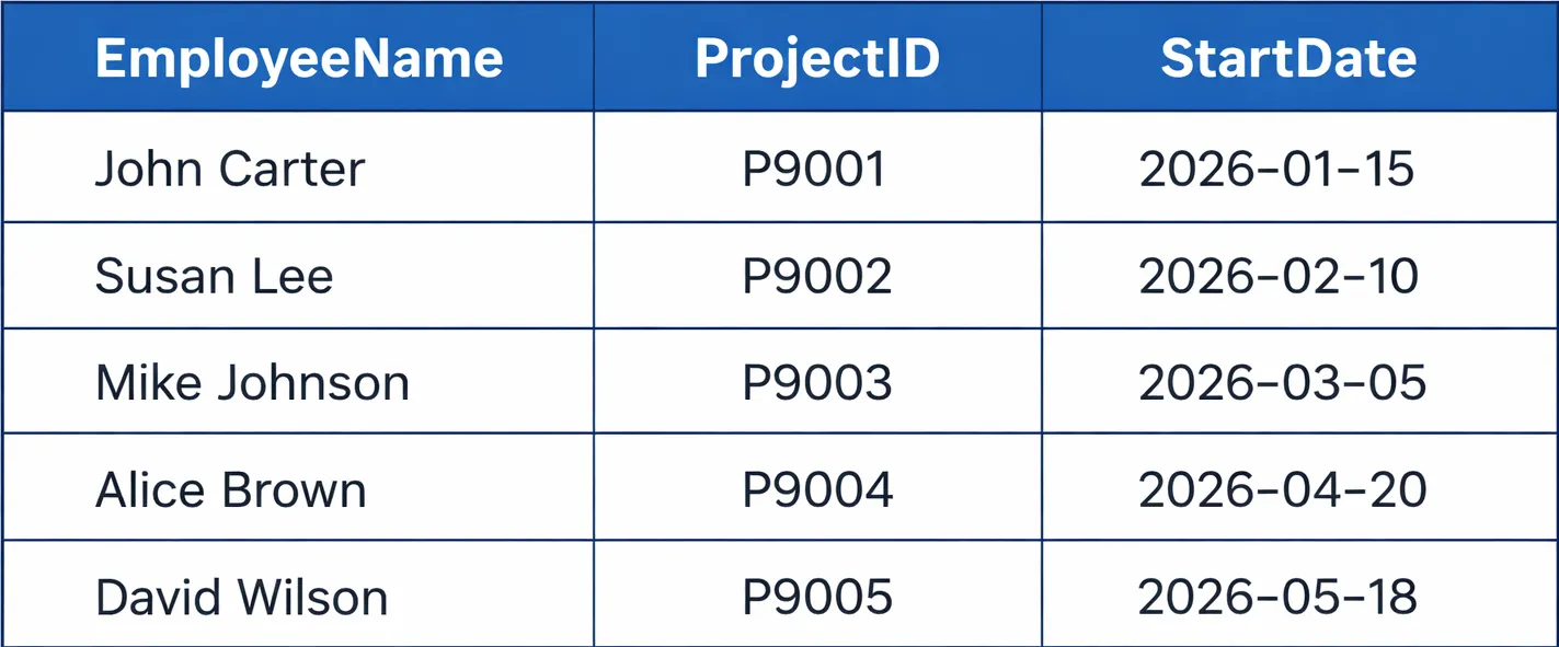
- Object-Oriented Model
The object-oriented model combines database technology with object-oriented programming. The system stores data as objects which contain both state information and operational methods. The object model enables applications to use standard inheritance and encapsulation mechanisms which help them manage complexity.
- NoSQL and Other Models:
Organizations require NoSQL database systems because their data requirements demand both extensive capacity and flexible storage. The systems operate without strict schema structures. Document stores use digital documents which follow the JSON structure as the basis for their record-keeping system while key-value stores provide basic search functions. Column-family stores use wide table structures while graph databases use node and edge models to represent their data.
{
   "EmployeeName": "John Carter",
   "Projects": [
    {
           "ProjectName": "AI Dashboard",
           "DurationMonths": 6
    }
   ]
}
Data Modeling Abstraction Levels
Data modeling is often described in three abstraction layers (sometimes called the three-schema architecture):
- Conceptual Data Model:
The highest level of this system provides complete data coverage without any technical aspects. The conceptual model defines high-level entities and relationships in business terms.
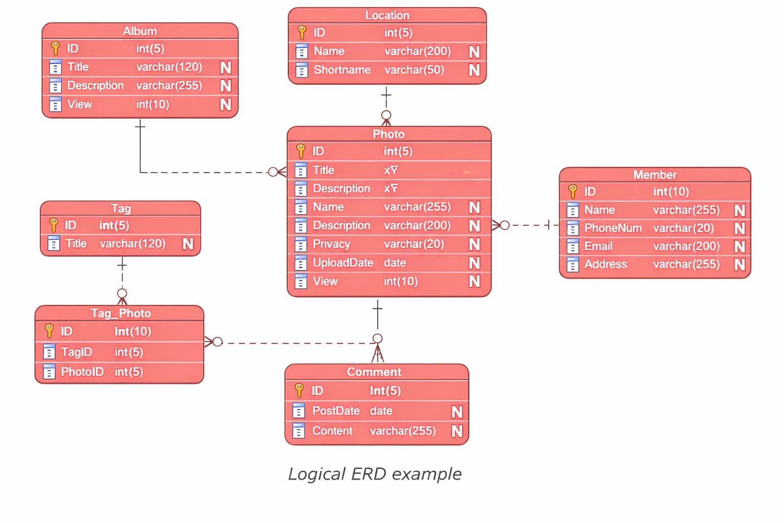
- Logical Data Model
The explanation expands through the identification of specific tables which contain particular columns and their associated data types while remaining independent from any particular database management system. The logical model takes the conceptual entities and lists their attributes and keys. The system displays primary keys together with foreign keys while it provides data type specifications that include integer and string types without addressing physical implementation details.
- Physical Data Model
The most complete level of detail connects to a specific database management system. The execution defines table structure through its implementation details which include specifications for column types and indexes and storage engines and partitions and other elements.
CREATE INDEX idx_order_customer ON Orders(CustomerID);
SELECT indexname, indexdef
FROM pg_indexes
WHERE tablename = 'orders';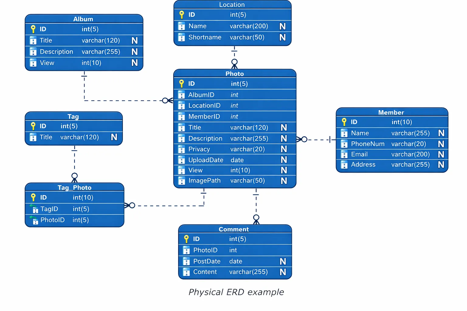
Key Components of a DBMS Data Model
The fundamental elements of data models serve as their essential components. The study of these components provides design capabilities that can achieve high performance and precise results.
Entities and Attributes: Entities represent real-world objects such as students or courses. Attributes describe entity properties like name, email, or course title. The attribute definitions provide clear descriptions which help to eliminate uncertainty and make data validation easier.
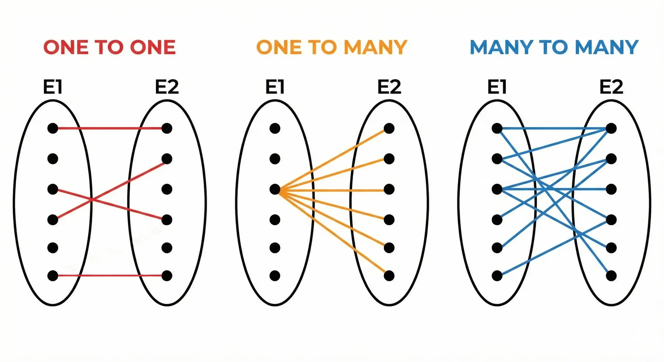
Relationships and Cardinality: Relationships establish the connections that link different entities. Cardinality defines the number of elements that can exist within a particular relationship.
The three main relationship types consist of:
- One-to-One relationships
- One-to-Many relationships
- Many-to-Many relationships
The system enforces constraints which safeguard data integrity through their established rules.
- Primary Key: The primary key functions as a unique identifier that distinguishes all records within a table. The system prevents duplicate entries while it provides fast access through indexing.
- Foreign Key: The foreign key establishes a connection between two associated tables. The system maintains referential integrity by blocking any attempts to create invalid links.
- Unique and Check Constraints: Unique constraints prevent duplicate values. Check constraints validate data ranges or formats.
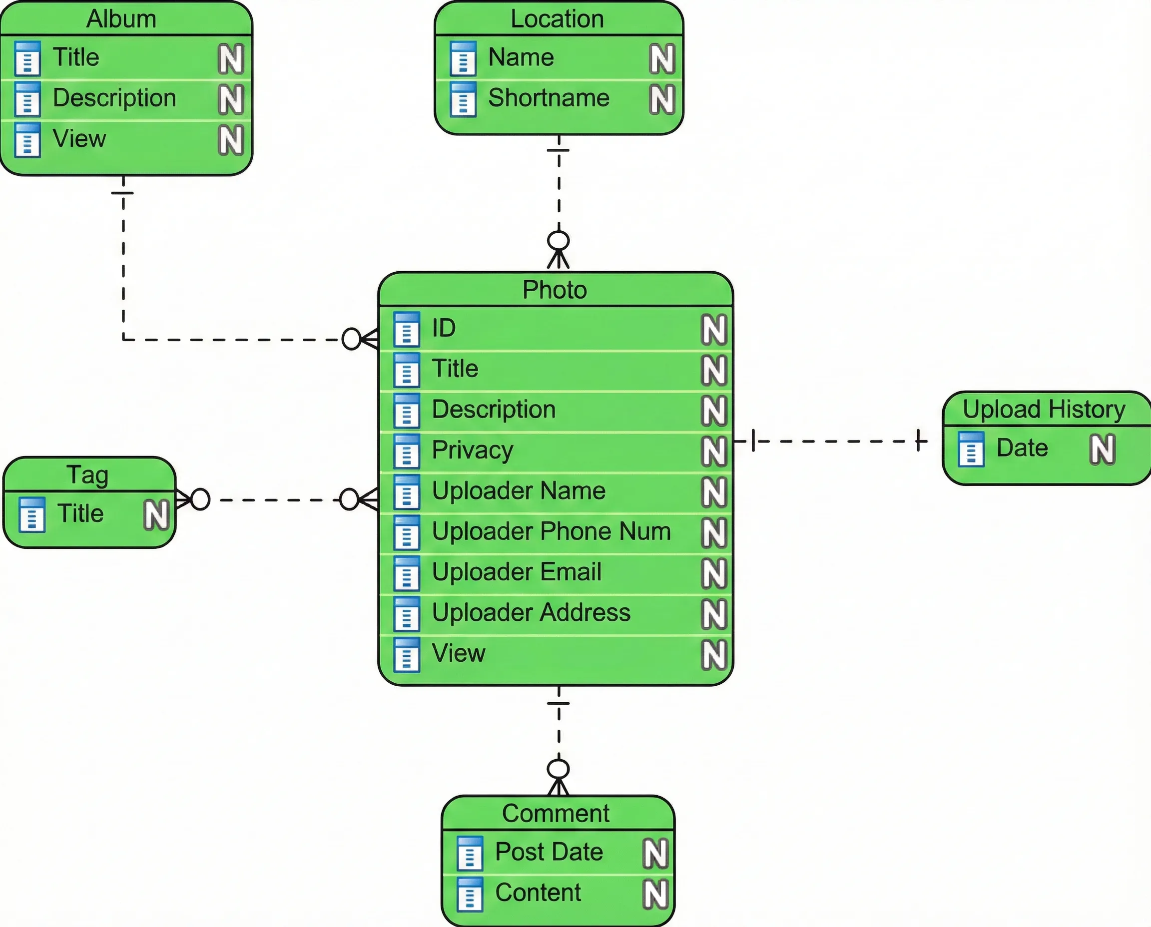
The Entity-Relationship (ER) Model
The Entity-Relationship (ER) model serves as a widely used method for creating conceptual models. The model enables the representation of actual objects through entities which display their internal structure. An entity corresponds to an object or concept (e.g. Student or Course), each with attributes (like StudentID, Name, Age).
Multiple entities connect through a relationship (like Enrollment) which shows their relationship by describing their mutual actions (for instance, “a student enrolls in courses”).
The ER model captures the essence of the data without committing to a table layout. The relationship between Student and Course shows a many-to-many connection which we can represent through a diagram.
A relational system transforms entities into tables while attributes become columns, and foreign keys serve to establish relationships between entities.
Key Components (Primary/Foreign Keys, Constraints)
- A Primary Key is a unique identifier for table rows. For example, StudentID uniquely identifies each student. A primary key column cannot contain NULL and must be unique. It ensures we can always tell records apart.
student_id INT PRIMARY KEY - A Foreign Key is a column or set of columns that links to the primary key of another table. This creates a referential integrity rule: the DBMS will not allow an enrollment that points to a non-existent student. In SQL, we might write:
FOREIGN KEY (StudentID) REFERENCES Student(StudentID) - Other constraints like NOT NULL, UNIQUE, or CHECK can enforce data rules (e.g., a grade column must be between 0 and 100). These constraints keep the data valid according to the model
ALTER TABLE Student
ADD CONSTRAINT unique_name UNIQUE (student_name);
Sample Student Management Database (MySQL Example)
So for demonstration let’s use a basic Student Management System. The system consists of three entities which are Student and Course and Enrollment that serves as the link between students and courses. We demonstrate the MySQL relational schema setup through the following process.
CREATE TABLE Student (
    StudentID INT AUTO_INCREMENT PRIMARY KEY,
    StudentName VARCHAR(100) NOT NULL,
    Major VARCHAR(50),
    Age INT
);

CREATE TABLE Course (
    CourseID INT AUTO_INCREMENT PRIMARY KEY,
    CourseName VARCHAR(100) NOT NULL,
    Department VARCHAR(50)
);

CREATE TABLE Enrollment (
    EnrollmentID INT AUTO_INCREMENT PRIMARY KEY,
    StudentID INT NOT NULL,
    CourseID INT NOT NULL,
    Grade CHAR(2),
    FOREIGN KEY (StudentID) REFERENCES Student(StudentID),
    FOREIGN KEY (CourseID) REFERENCES Course(CourseID)
);
In this schema:
- The StudentID and CourseID serve as primary keys for their respective tables which results in every student and course receiving distinct identification numbers.
- The Enrollment table has two foreign keys (StudentID, CourseID) that reference the respective primary keys. This enforces that every enrollment entry corresponds to a valid student and course.
- The AUTO_INCREMENT attribute (MySQL-specific) automatically generates unique IDs. The NOT NULL constraint ensures these ID fields must have values.
- Other constraints like
NOT NULLon names prevent missing data.
This design is helps in creating normalization, so student and course information isn’t duplicated in each enrollment row, reducing redundancy
Inserting Sample Data
INSERT INTO Student (StudentName, Major, Age) VALUES
    ('Alice', 'Biology', 20),
    ('Bob', 'Computer Science', 22);

INSERT INTO Course (CourseName, Department) VALUES
    ('Database Systems', 'Computer Science'),
    ('Calculus I', 'Mathematics');

INSERT INTO Enrollment (StudentID, CourseID, Grade) VALUES
    (1, 1, 'A'),
    (1, 2, 'B'),
    (2, 1, 'A');
These inserts add two students and two courses. Then we add enrollments linking them: for example, (1,1,’A’) means Alice (StudentID=1) takes Database Systems (CourseID=1) and earned an A grade. MySQL enforces foreign key constraints which prevent users from adding enrollments that contain non-existent StudentID or CourseID values. Our sample data exists in 3rd Normal Form (3NF) because every data element exists as a single storage item.
Normalization in DBMS
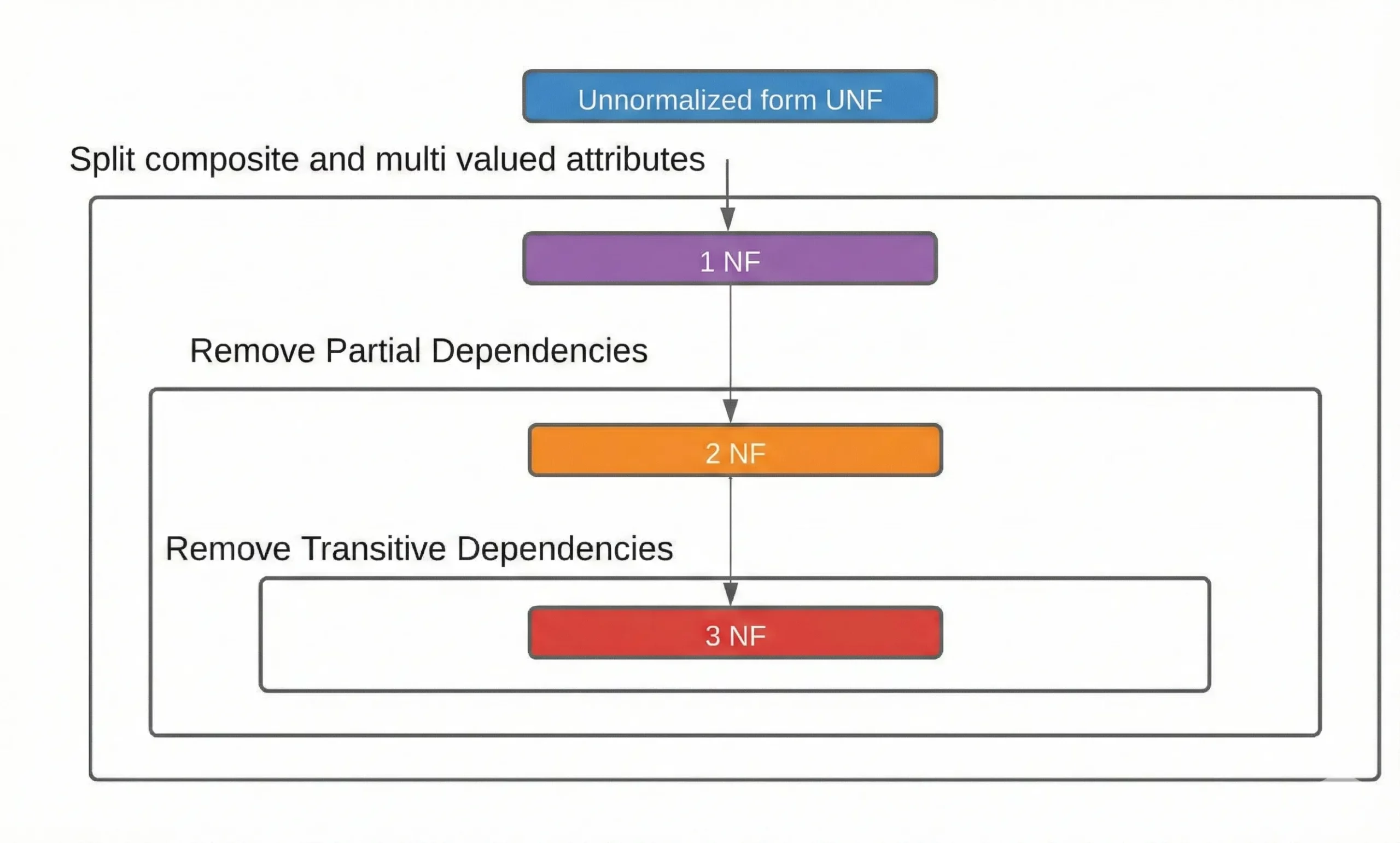
Normalization organizes tables through its process which eliminates duplicate data and prevents issues during updates. The normal forms rules which we utilize to implement our system include the following definitions:
- 1NF (First Normal Form): Each table cell should hold a single value (no repeating groups).
- 2NF (Second Normal Form): In tables with composite keys, non-key columns must depend on the whole key, not just part of it.
- 3NF (Third Normal Form): Non-key columns must depend only on the primary key, not on other non-key columns.
The process of normalization brings two benefits because it decreases data duplication which leads to storage savings and prevents data inconsistencies while making data maintenance easier. The Student table serves as the only source for updating Alice’s major and age information. The process of data normalization creates benefits but its highly standardized schemas require multiple JOIN to build report data which causes delays in executing complex queries.
Advantages and Disadvantages of Data Models
| Advantages | Disadvantages |
| Ensure accurate and consistent representation of data | Initial design requires significant time for complex systems |
| Reduce data redundancy and avoid duplication | Large schemas become difficult to understand |
| Primary and foreign keys establish clear relationship definitions | Minor structural changes can impact the entire system |
| Improve data integrity through constraints and rules | Requires expertise in both domain knowledge and database systems |
| Make databases more understandable for developers and analysts | Highly dynamic systems may suffer from over-engineered models |
| Support ongoing maintenance and future expansion |
Conclusion
The foundation of any dependable database system depends on its data models which serve as fundamental components. They assist in creating databases which meet actual needs through their structured design and ability to handle increasing data volumes and achieve operational efficiency. Understanding conceptual and logical and physical models enables you to manage system data behavior. Database maintenance becomes simpler and query execution speeds up through proper implementation of modeling and normalization and indexing techniques. Data modeling requires investment of time because it benefits both small applications and large enterprise systems.
Frequently Asked Questions
Q1. What is the purpose of a data model in DBMS?
A. It defines how data is structured, related, and constrained, serving as a blueprint for building reliable and efficient databases.
Q2. What is the difference between conceptual, logical, and physical models?
A. Conceptual focuses on business entities, logical defines tables and keys, and physical specifies implementation details like data types and indexes.
Q3. Why is normalization important in database design?
A. It reduces redundancy, prevents update anomalies, and improves data integrity by organizing data into well-structured tables.
Hello! I'm Vipin, a passionate data science and machine learning enthusiast with a strong foundation in data analysis, machine learning algorithms, and programming. I have hands-on experience in building models, managing messy data, and solving real-world problems. My goal is to apply data-driven insights to create practical solutions that drive results. I'm eager to contribute my skills in a collaborative environment while continuing to learn and grow in the fields of Data Science, Machine Learning, and NLP.